- Connection
- English


BCP3 3-relays box, under the bonnet.
BSI cabin comfort C. U..
1032 cartridge fuses additional box / battery.
PSF1 fuse and relay box / motor.
0004 centre display.
1220 motor temperature sensor.
1320 engine control unit - ECU.
1510 motoventilator of the engine coolant circuit.
1522 relay of the engine coolant motor-driven fan.
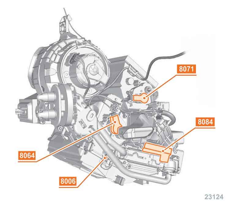
8006 temperature sensor of the evaporator.
8007 A/C refrigerant high pressure HP sensor.
8020 A/C compressor.
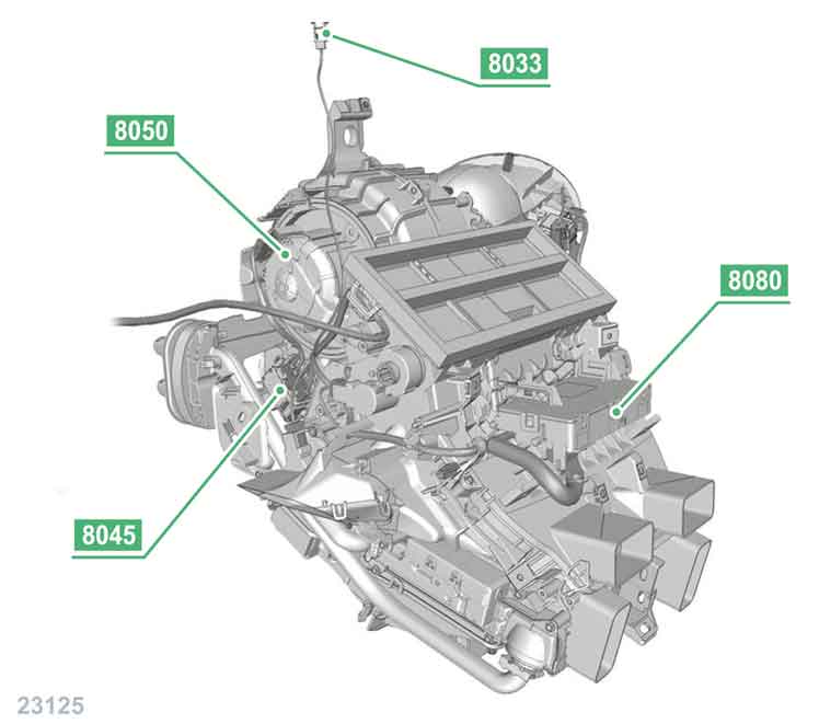
8033 sunlight sensor.
8045 cabin blower control module.
8050 cabin blower.
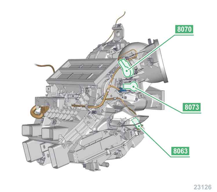
8063 air mix motor / right side.
8064 air mix motor / left side.
8070 air recirculation motor.
8071 air distribution flap servomotor -> central.
8073 air distribution flap servomotor -> feet / defrost.
8080 A/C control unit.
8084 heating resistances of the auxiliary heater.
84C6 A/C control interface.
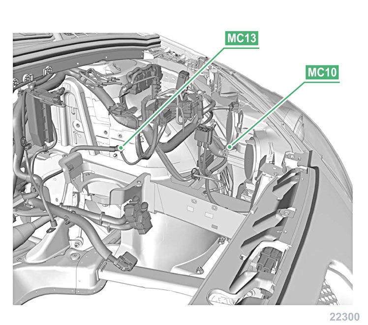
MC10 earth wing shield at the front/left side of the motor compartment.
MC13 earth wheel arch / left side.
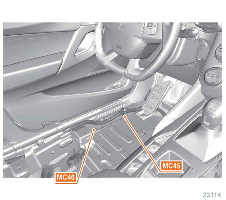
MC45/MC46 earth door frame / on the driver side.
MC47 earth / foot of the door pillar / central / left side.
MC51 earth.
* petrol engine.
** diesel engine.

F21 fuse of the A/C control unit.


BPGA / 1032 cartridge fuses additional box.
F5 cartridge fuse of the engine coolant motor-driven fan.
F10 cartridge fuse of the cabin blower C. U..
F11 cartridge fuse of the cabin blower C. U. -> rear.

PSF1 motor compartment fuses box.
F2 fuse of the motor-driven fan contol unit for the engine coolant circuit.
F14 fuse of the external control solenoid valve.
F26 fuse of the A/C compressor clutch.
The outside temperature must exceed 15°C.
Cabin filter in perfect shape (if fitted).
Connect the inspection equipment to the high and low pressure couplings.
If not, reload the cooling circuit with the proper gas quantity.
No one should stay inside the vehicle during the controlling process.
Doors closed, windows avant open.
Motor bonnet closed.
Hot engine (after one engagement of the motor-driven fan).
A-C running.
Air distribution : all air vents at maxi opening.
Regulation : automatic position.
Cabin air distribution : recirculation.
Air temperature in the cabin : maximum cold.
Blower speed : maxi.
Keep the engine speed at 2000 rpm.
Read the pressures as soon as stabilization occurs.
The readings should be in line with the reference values.
| outside temperature (°C) | input pressure of the compressor (LP) bar | compressor output pressure (HP) bar |
|---|---|---|
| 20,00 | 2,00 ±0,10 | 10,60 ±4,10 |
PSF1 27 pins connector.

PSF1 6 pins connector NR black colored.

40 pins connector.

6 pins connector.


BSI fuse and relay box cabin.
BSI 16 pins connector VE green colored.

BSI 16 pins connector NR black colored.

BSI 16 pins connector GR grey colored.

BSI 35 pins connector NR black colored.

BSI 60 pins connector.


70 pins connector.

120 pins connector.

The system uses distribution motors of the type.
The group of the air distribution motors is monitored in parallel by the A/C C. U..
The 2 stepper coils with pole reversal are supplied by a joint power supply.
Activate the air distribution motors through the A/C control panel in the cabin.
Disconnect the connector.

The distribution of the regulation among four zones offers full choice to the rear passengers.
The modul 8045 / 80A6 receives from the A/C unit 8080 a variable voltage, which varies according to the requested motorfan speed.
This rectangular signal is built as a % variable duty cycle; the cycle variation represents the rotational speed regulation of the cabin blower (fresh air).
1 cabin blower control -.
2 cabin blower control +.
3 feed system cabin blower control module +12v.
4 feedback signal of the fan speed.
5 pulsated modulated signal cabin blower control %.
6 earth.
The system uses distribution motors of the type.
The group of the air distribution motors is monitored in parallel by the A/C C. U..
The 2 stepper coils with pole reversal are supplied by a joint power supply.
Activate the air distribution motors through the A/C control panel in the cabin.
Disconnect the connector.

This is a NTC sensor (negative temperature coefficient); as the temperature increases, the more its resistance decreases.

A light sensor is on the dashboard close to the windscreen. The signal changes according to the occultation or the lighting of the sunlight sensor.
It allows to dampen the reading when the lighting rate is weak (tunnel, woods area, driving by night) and to reinforce the reading when the lighting rate is stronger.
1 sunlight sensor signal mA.
2 earth.
Insulation test - to earth - for the socket pins.
Insulation test - to + - for the socket pins.
The system uses distribution motors of the type.
The group of the air distribution motors is monitored in parallel by the A/C C. U..
The 2 stepper coils with pole reversal are supplied by a joint power supply.
Activate the air distribution motors through the A/C control panel in the cabin.
Disconnect the connector.

The linear pressure sensor (piezo electric) measures the cooling fluid pressure.
It differs from the 3-ways pressure switch by delivering a linear signal.
The pressure sensor data are transferred to the injection C. U..
The information is transferred via multiplex link to the cabin C.U. (BSI).
1 earth.
2 linear voltage signal : 0,5 4,5 volts.
3 supply voltage : 5 volts.
Linear voltage signal : 0,5 +/- 0,1 volts 1 bar.
Linear voltage signal : 1,6 +/- 0,3 volts 10 bars.
Linear voltage signal : 2,5 +/- 0,3 volts 15 bars.
Linear voltage signal : 4,5 +/- 0,3 volts 31 bars.
The solenoid control valve is electically piloted by the A/C C. U..
It receives a control signal which allows to force a differential pressure level in line with a swash plate position, that is to say with a clearly defined cold output of the compressor.
The control is achieved through a pulsated modulated current . The cubic capacity will result from the duty cycle of this signal.
The solenoid valve signal changes according to the evaporator exit temperature and to the pressure in the HP circuit.